Optimize Tile Rendering on the Earth Ellipsoid with Culling and SSE
2024-07-17

Hello. This is Sasaki from Eukarya.
Our company is developing a new 3D map engine. A map engine is a system that displays a globe in a 3D space like Google Earth, allowing users to see more detailed images as they zoom in. It is used not only for maps like Google Earth but also for visualizing location information data. Examples of existing map engines include CesiumJS and Mapbox GL JS.
To create a globe-like appearance in 3D space, it's necessary to attach large images on the Earth's ellipsoid. To ensure clear resolution when zoomed in, the application needs to retrieve and display images divided into tiles, known as raster tiles.
This time, we have implemented this feature in our map engine, so I will briefly introduce the mechanism.
Mechanism for Drawing Tiles on the Earth's Ellipsoid
As mentioned earlier, to draw images on the Earth's ellipsoid at resolutions according to the camera's zoom level, we use data called raster tiles. These tiles are divided to ensure each tile is a certain size, and they are structured to be retrievable based on Z/X/Y coordinates. Note that Z comes first as a convention in raster tiles.
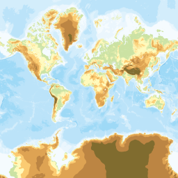
For example, looking at the standard map from the Geospatial Information Authority of Japan:
When the coordinates are 0/0/0, the image returned is the entire Earth.
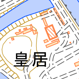
Now, let's look at the data at zoom level 17. The image shows the Imperial Palace with high detail. This image is 17/116418/51611, indicating a high-detail image based on the large numerical values.
These coordinates start from 0/0/0 and recursively divide each tile into four.
For example, at zoom level 1, there are four tiles: 1/0/0, 1/0/1, 1/1/0, 1/1/1. Similarly, at zoom level 2, each tile of zoom level 1 is further divided into four tiles.
Repeatedly doing this means at zoom level 20, we need to draw 4 to the power of 20 tiles. However, rendering this massive number of tiles in real-time is challenging. Therefore, it is necessary to select and render only the required tiles efficiently.
Quadtree
The structure where tiles are divided into four from the root is similar to a data structure called a Quadtree. This data structure is often used as a method to efficiently manage tiles. By using this tree structure, we can efficiently trace only the tiles within the camera's visible range.
Since it is a tree structure, the premise that if the parent element is invisible, the child elements are always invisible stands, avoiding unnecessary searches.
A more detailed explanation is left to another article, “Data Structure and Mechanism of Spatial Partitioning in 3DCG”.
Frustum Culling
Frustum culling is a mechanism to cull objects outside the camera's frustum (viewing pyramid). It is a common technique in 3DCG. The frustum represents the camera's visible range in a pyramid-like shape as shown in the image below.
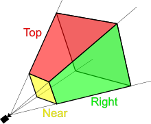
To perform frustum culling, calculate the distance between the bounding box of the object and the planes forming the frustum. If the bounding box is inside the frustum, render it; otherwise, don’t. This avoids rendering tiles outside the camera's frustum.
Horizon Culling
However, in a map engine, this alone presents a problem.
When viewing the Earth's ellipsoid from afar, the entire Earth should be visible. For this, the frustum must be a very large object, causing unnecessary rendering of tiles beyond the horizon.
To solve this issue, One can use an algorithm called Horizon culling.
A detailed explanation is left to Cesium's article, "Horizon Culling". This mechanism helps avoid rendering tiles that were insufficiently culled by frustum culling.
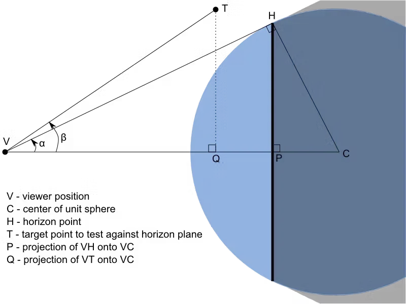
Below is a simple explanation of the horizon culling mechanism with a diagram. Here, point T is the target point.
- Check if point T is inside the triangle VCH. To calculate this, find the projection point Q from the dot product of VT and VC.
- Similarly, find point P and compare distances between VQ and VP, confirming if it is in front of the ellipsoid. If not, skip rendering.
- Using the relationship between vector dot products and the cosine theorem, calculate the cosines of α and β, and compare them. If β is larger, consider point T out of range and skip rendering.
Consideration is needed on how to determine point T.
If you fix point T as the center of the object to be occluded, it may be unintentionally culled when displaying terrain.
Therefore, as mentioned in "Computing the horizon occlusion point", it is important to calculate an appropriate point.
Screen Space Error (SSE)
Screen Space Error (SSE) is one of the methods to properly display the Level of Detail (LOD) according to the position of the camera and the model. LOD represents the number of polygons in the model; the higher the LOD, the higher the resolution and the more polygons the model has.
In a map engine, it is necessary to properly render hundreds of thousands of polygons to display the entire Earth's tiles and terrain. For example, when rendering raster tiles, you want to display tiles with appropriate LOD according to the distance between the camera and the tiles. SSE is used to achieve this.
In our map engine, we are implementing SSE based on Cesium's logic. Here, I will briefly explain the SSE mechanism used for tile rendering based on Cesium's code. For details, refer to "Massive-Terrain Rendering - 3D Engine Design for Virtual Globes".
Accurate SSE calculation is necessary for each model, but the Cesium-based SSE implemented this time considers the terrain as a simple model.
-
Calculate the Geometric error representing the error between high-resolution and low-resolution model points (reference). Pre-calculate the Geometric Error of tiles at zoom level 0 (reference) and use that value to calculate the error for each zoom level (reference).
const levelZeroGeometricError = (ellipsoid.maximumRadius * 2 * Math.PI * TerrainProvider.heightmapTerrainQuality) / (tileImageWidth * numberOfTilesAtLevelZero); const maxGeometricError = levelZeroGeometricError / (1 << level); -
Scale the Geometric error by the screen height to find the number of pixels (reference).
const x = maxGeometricError * screenHeight; -
Calculate the vertical field of view according to the aspect ratio. Since fov is the horizontal angle, if the screen is vertically long, it can be approximated as is, but if it is horizontally long, the exact angle needs to be calculated (reference). Also, calculate the ratio of the frustum front width to the distance using the tangent of half the vertical field of view (reference).
const fovy = aspectRatio <= 1 ? fov : Math.atan(Math.tan(fov * 0.5) / aspectRatio) * 2.0; const sseDenominator = 2.0 * Math.tan(0.5 * fovy); -
Multiply the distance between the tile and the camera by
sseDenominatorobtained from the camera's field of view to find the display width of this tile on the screen (reference).const w = distance * sseDenominator; -
Divide the number of pixels found by the display width, and further divide by the pixel resolution to find SSE.
const sse = x / w / window.devicePixelRatio; -
Compare this error with the maximum allowable SSE, and if it is smaller than the maximum value, render the corresponding tile (reference).
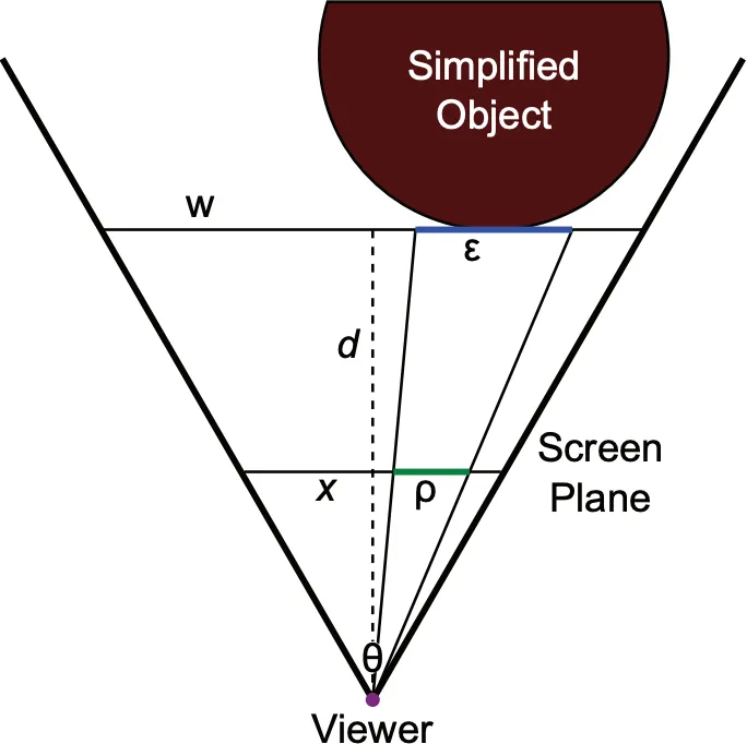
In the figure below, ρ represents SSE. ε is the Geometric Error, x is the number of pixels, d is the distance to the model, θ is the field of view angle, and w is the display width.
https://virtualglobebook.com/3DEngineDesignForVirtualGlobesSection121.pdf
Conclusion
Using these algorithms, we can render tiles at a certain speed.
However, this is merely logic for selecting the appropriate tiles to render. Therefore, it is necessary to perform more advanced processing, such as rendering complex terrains on the selected tiles and filling gaps between tiles to render them beautifully.
Developing a map engine requires endless learning…!
Eukaryaでは様々な職種で採用を行っています!OSSにコントリビュートしていただける皆様からの応募をお待ちしております!
Eukarya is hiring for various positions! We are looking forward to your application from everyone who can contribute to OSS!
Eukaryaは、Re:Earthと呼ばれるWebGISのSaaSの開発運営・研究開発を行っています。Web上で3Dを含むGIS(地図アプリの公開、データ管理、データ変換等)に関するあらゆる業務を完結できることを目指しています。ソースコードはほとんどOSSとしてGitHubで公開されています。
➔ Re:Earth / ➔ Eukarya / ➔ note / ➔ GitHub
Eukarya is developing and operating a WebGIS SaaS called Re:Earth. We aim to complete all GIS-related tasks including 3D (such as publishing map applications, data management, and data conversion) on the web. Most of the source code is published on GitHub as OSS.