Rendering Polygons along the Terrain using a Stencil Test
2025-01-31

Hello, this is Sasaki from Eukarya.
Our company is developing a new 3D map engine. A map engine, similar to Google Earth, displays a globe in three-dimensional space and provides more detailed images as you zoom in. In addition to serving as a map, such an engine can be used for visualizing geospatial data. Existing examples of mapping engines include CesiumJS and Mapbox GL JS.
The map engine supports terrain visualization, allowing realistic visual representations of the real world.
This time, I’d like to introduce a feature we've implemented for rendering polygons and lines along the surface of terrain.
Objective
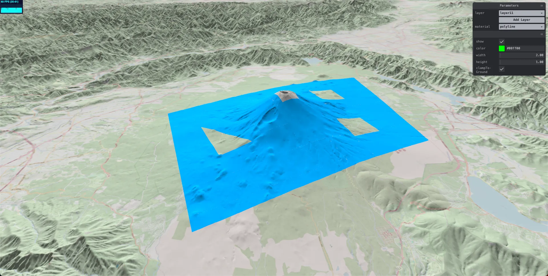
We aim to render arbitrary polygons along the surface of complex terrains, as shown in the following image:
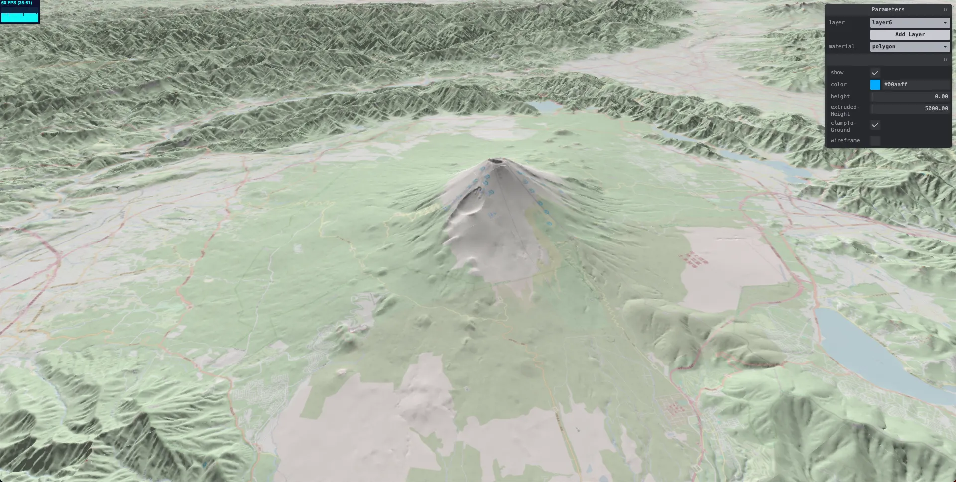
Here’s an example of a polygon rendered along Mount Fuji’s terrain. The visualization remains consistent even when the terrain’s LOD (Level of Detail) changes.

Demo Code
You can find a demo in the repository linked below:
Available Methods
While implementing this type of rendering may seem straightforward at first glance, performance considerations make it more challenging.
The simplest approach involves deforming the polygon's vertices to conform to the terrain. However, with complex polygon shapes, this approach quickly becomes computationally expensive.
Another method is to render the polygon onto a texture and map that texture onto the terrain mesh. While this works in some cases, rendering large polygons can result in low resolution and high memory usage.
A more effective solution is to use stencil tests, as described in these papers:
- "Rendering 3D Vector Data Using the Theory of Stencil Shadow Volumes"
- "Efficient and Accurate Rendering of Vector Data on Virtual Landscapes"
Stencil tests allow polygons to conform to terrain without requiring complex shader implementations or heavy CPU resources.
Stencil Test Overview
Stencil tests determine whether specific fragments (pixels) should be rendered.
During a stencil test, the stencil buffer’s values are updated for each fragment based on conditions such as:
- Failing the stencil test
- Failing the depth test
- Passing the depth test
The final stencil buffer values dictate whether to display the fragment.
Using stencil tests, you can control the rendering of fragments based on how the mesh overlaps.
Implementation Using Stencil Tests
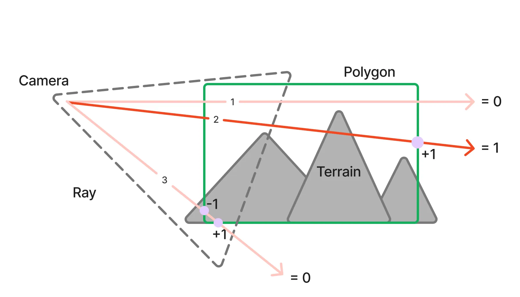
Here’s the basic approach derived from the mentioned papers:
-
Create a polygon covering the terrain
A polygon with both front and back faces is created to wrap around the terrain. The front face is visible to the camera, while the back face is occluded by the terrain.
-
Render the back face with a stencil test
- When a back face fails the depth test (i.e., hidden by the terrain), increment the stencil buffer.
-
Render the front face with a stencil test
- When a front face fails the depth test, decrement the stencil buffer.
-
Render the back face as the final step
- Display fragments with non-zero stencil buffer values, disabling the depth test. This ensures correct rendering even when the camera is inside the polygon.
Here’s a diagram summarizing the process:
An example implementation is as follows. Please refer to the demo repository for the complete code.
// gl: WebGLRenderer, m: Mesh, scene: Scene, camera: Camera

// Back face
m.stencilFunc = AlwaysStencilFunc;
m.stencilFail = KeepStencilOp;
m.stencilZPass = KeepStencilOp;
m.stencilZFail = IncrementWrapStencilOp;
m.side = BackSide;
m.colorWrite = false;
m.depthWrite = false;
m.stencilWrite = true;
m.depthTest = true;
gl.render(scene, camera);

// Front face
m.stencilZFail = DecrementWrapStencilOp;
m.side = FrontSide;
gl.render(scene, camera);

// Final rendering
m.stencilFunc = NotEqualStencilFunc;
m.stencilFail = ZeroStencilOp;
m.stencilZFail = ZeroStencilOp;
m.stencilZPass = ZeroStencilOp;
m.side = BackSide;
m.colorWrite = true;
m.depthTest = false;
gl.render(scene, camera);
Adding Shadows
Simply using a stencil test to cut out polygons will not add shadows, as shown in the image below:
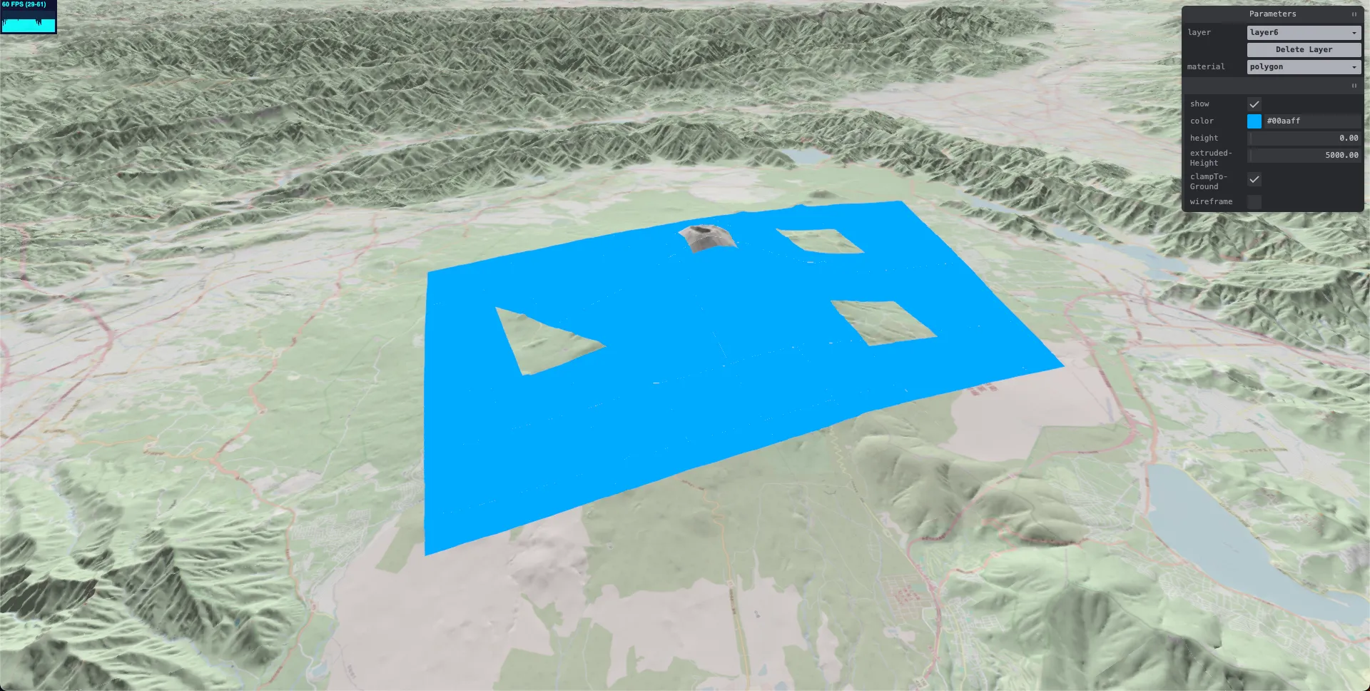
To add shadows, terrain normals are used. First, render only the terrain normals to generate a normal map. Then, use this normal map to calculate the normals and apply lighting to the polygons, resulting in shadows, as shown below:
Various methods exist to compute a normal map. Here, we use Three.js's MeshNormalMaterial to extract the terrain normals (code reference):
import { ForwardedRef, forwardRef, useEffect, useRef } from "react";
import { Mesh } from "three";
import { TEXTURE_LOADER } from "./loaders";

const DISPLACEMENT_MAP = TEXTURE_LOADER.load("displacementmap.png");
const DISPLACEMENT_MAP_NORMAL = TEXTURE_LOADER.load("displacementmapnormals.png");

type Props = {
    scale?: number;
    normal?: boolean;
};

export const Terrain = forwardRef(
    ({ scale = 30, normal }: Props, forwardedRef: ForwardedRef<Mesh | null>) => {
        const ref = useRef<Mesh | null>();
        useEffect(() => {
            ref.current?.rotateX(-Math.PI / 2);
        }, []);

        return (
            <mesh
                ref={(r) => {
                    if (typeof forwardedRef === "function") {
                        forwardedRef(r);
                    } else if (forwardedRef) {
                        forwardedRef.current = r;
                    }
                    ref.current = r;
                }}
            >
                <planeGeometry args={[200, 200, 100, 100]} />
                {normal ? (
                    <meshNormalMaterial
                        displacementScale={scale}
                        displacementMap={DISPLACEMENT_MAP}
                        normalMap={DISPLACEMENT_MAP_NORMAL}
                    />
                ) : (
                    <meshPhongMaterial
                        color={0xaaaaaa}
                        displacementScale={scale}
                        displacementMap={DISPLACEMENT_MAP}
                        normalMap={DISPLACEMENT_MAP_NORMAL}
                    />
                )}
            </mesh>
        );
    }
);
Next, we pass the computed normal map to the polygon mesh (code reference):
// gl: WebGLRenderer, scene: Scene, mesh: Mesh, enabled?: boolean, normalMap?: Texture
const defaultAutoClear = gl.autoClear;
gl.autoClear = false;

const m = mesh.material;
if (!(m instanceof Material)) return;

if ("normalMap" in m) {
    m.normalMap = normalMap;
}

scene.add(mesh);

// Perform the stencil test afterward
For the polygon mesh, we use an extended version of Three.js's MeshLambertMaterial called DrapedLambertMaterial:
import { MeshLambertMaterial, WebGLProgramParametersWithUniforms } from "three";

export class DrapedLambertMaterial extends MeshLambertMaterial {
    onBeforeCompile(parameters: WebGLProgramParametersWithUniforms): void {
        parameters.fragmentShader = parameters.fragmentShader.replace(
            "#include <normal_fragment_maps>",
            `
vec2 uv = gl_FragCoord.xy / vec2(textureSize(normalMap, 0));
vec3 mapN = texture2D(normalMap, uv).xyz * 2.0 - 1.0;
mapN.xy *= 3.0;
normal = normalize(mapN);
`
        );
    }
}
This material overrides the process of retrieving normals from the normal map. Instead of using vertex-based UV coordinates, it calculates UVs relative to the position in the normal map.
This approach ensures accurate lighting and shading of polygons draped over the terrain.
Conclusion
By leveraging stencil tests, we’ve implemented a method to render polygons that conform to complex terrains without requiring complex shaders or CPU resources. Adding terrain normals enabled us to achieve realistic shading effects.
Feel free to explore the possibilities of stencil-based rendering for advanced visualization!
Eukaryaでは様々な職種で採用を行っています!OSSにコントリビュートしていただける皆様からの応募をお待ちしております!
Eukarya is hiring for various positions! We are looking forward to your application from everyone who can contribute to OSS!
Eukaryaは、Re:Earthと呼ばれるWebGISのSaaSの開発運営・研究開発を行っています。Web上で3Dを含むGIS(地図アプリの公開、データ管理、データ変換等)に関するあらゆる業務を完結できることを目指しています。ソースコードはほとんどOSSとしてGitHubで公開されています。
➔ Re:Earth / ➔ Eukarya / ➔ note / ➔ GitHub
Eukarya is developing and operating a WebGIS SaaS called Re:Earth. We aim to complete all GIS-related tasks including 3D (such as publishing map applications, data management, and data conversion) on the web. Most of the source code is published on GitHub as OSS.